-
×
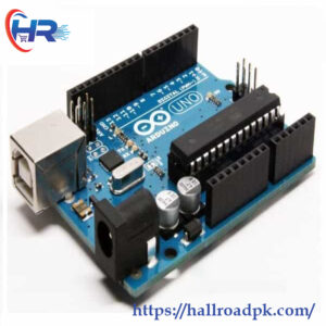
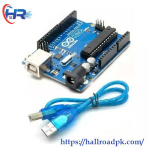 Arduino UNO R3 with Cable – ATmega328 Microcontroller Board for Ultimate DIY Projects
1 × ₨1,900.00
Arduino UNO R3 with Cable – ATmega328 Microcontroller Board for Ultimate DIY Projects
1 × ₨1,900.00
Subtotal: ₨1,900.00
 Arduino UNO R3 with Cable – ATmega328 Microcontroller Board for Ultimate DIY Projects
1 × ₨1,900.00
Arduino UNO R3 with Cable – ATmega328 Microcontroller Board for Ultimate DIY Projects
1 × ₨1,900.00 Subtotal: ₨1,900.00
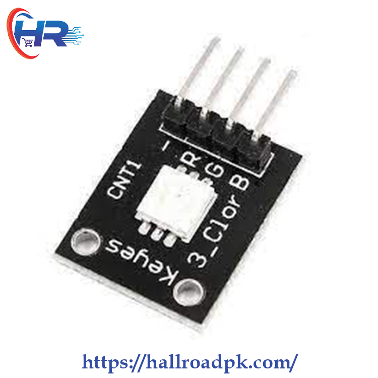
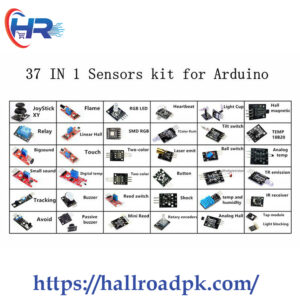
This is the SMD RGB LED Common Cathode Module, This module has 3 separate LEDs the Red, Green, and Blue which can be individually driven by applying a voltage to the appropriate module pin this example code uses the Arduino analogWrite(PWM) function to cycle through the full possible output colors this smd led module is capable of producing a rainbow color scheme.
There is a 4-pin header on the assembly for making connections.
1 x 4 Header
NOTE: On some modules, we have found the labeling on the R and G channels to be swapped. If you go by our connection diagram, you should be good to go.
| Maximum Ratings | ||
| Vcc | 5V | |
| IMax | Maximum Current Draw per LED | < 30mA |
| Operating Ratings | ||
| Voltage Drop | Red LED | 1.8-2.4V |
| Green LED | 2.8 – 3.6V | |
| Blue LED | 2.8 – 3.6V | |
| Polarity | Common Cathode | |
| Dimensions | L x W (PCB) | 20 x 15mm (0.75 x 0.60″) |

There are no reviews yet.